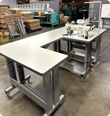

We're looking at the detailed assembly process for a single needle industrial sewing machine like this DDL8700 from Prizzi Sewing. Your shipment will come in four boxes including the machine head, leg set, as well as the tabletop that Prizzi is really known for, plus a nice servo motor. And although we're featuring the very popular Juki DDL8700, the process would be very similar with any single needle non-walking foot machine.
Assembling K-Legs
Let's start by assembling the legs, which in this case is an adjustable K-Leg set: the rear brace and the lower brace, as well as the foot pedal with main hardware pack, and a sewing drawer plus some additional hardware. Adjust your K-Leg height as desired.
Now this set is adjustable from 25 inches all the way up to 32 inches, but remember those Prizzi tabletops will add another inch and a half to your finished height. Then we'll lock in the height on those adjustable K-Legs, and for that you want the large bolts, lock washer, and flat washer coming from the outside. On the inside there's a specialty washer, and that just keeps the fastener from turning as you secure it.
If you're not sure what height you need, it's a good guess to go with the lowest hole and slide the mechanism to the highest position. That will give you a final table height including the top of about 30 inches. And you'll secure those fasteners with a 22 millimeter socket or an adjustable wrench.

Usually K-Legs are easiest to assemble upside down. You'll notice that the tables come pre-drilled on the underside to align with the leg set, so I like to just roughly clamp that in position. If you don't have clamps, maybe you can just get a helper.
Now luckily there's no rider left to this K-Leg set, so they can go on either side, but the next step is to add this rear brace. And you'll see how that shape kind of engages with the leg set as the holes line up, and you'll install that with standard fasteners, washer, and nut. And those will install with 17 millimeter tools.
Now it's time to install that bottom brace, and the tabs on that go on the outside of the frame, so just set that in place. And your fasteners there are the carriage bolts, a washer, and nut. There's a good range of adjustment there, and usually the preferred position is in the front slot slid all the way to the back of the table.
And once both sides are attached, you can go ahead and secure the fasteners with a 17 millimeter socket or wrench. You can fully pre-drill for those quarter inch fasteners if you like, makes installation a little bit easier. And those will install with a number three Phillips bit.
And you'll want at least four fasteners on each side for a sturdy connection. Now that the leg set is secure and attached to the table, you can release those temporary clamps. That belt slot is an important landmark for orienting your leg set correctly.
This will always point towards the back of the table. Momentarily tip the table on its side just to add those carriage bolts for the motor installation.
Install Servo Motor
Your servo motor installation kit comes with carriage bolts, vibration dampeners, the pulley guard, as well as fasteners for that guard, and then some extra parts that you won't need right now.

A spare cork brake, and a spare set of brushes for that servo motor, plus some wire clips. Install the three carriage bolts from the top side with a small hammer. You'll notice that everything comes nicely pre-machined on these Prizzi tables like the pockets for the hinges and the head supports, as well as your belt slot and holes for the mechanic's kickstand and thread stand.
Then we'd like the table upside down again to complete assembly. Install the servo motor, and the order there is the vibration dampeners, and then the motor, followed by washers, lock washers, and nut. Next, we need to visually align that pulley with the belt slot.
Then we'll tighten down those nuts with a 14 millimeter wrench. Mount the switch box here, just set back from the front edge of the table, and on the same side as the belt slot. And of course, we'll drive that by hand to avoid damage to the switch box.
And then manage your wires with the included clips to keep them away from the belt and pulley. Now that the motor position is fixed left to right, we can go ahead and install that foot pedal.
Foot Pedal Installation
On either side of the foot pedal, there's a post, and the first thing you install is this special nylon washer, and that just helps to reduce noise and friction between the bracket and the pedal.

There's also a treadle rod bracket that attaches with these two small bolts. Those are 10 millimeter fasteners, and you can see there's a nice range of adjustment with those wide slots. And those foot pedal brackets attach with bolts, fender washers, and nuts.
It's very important to use those fender washers, just so nothing can come loose in regular operation. And the slotted holes in that lower brace does give you a fair bit of adjustment. And the foot pedal position is determined in part by operator preference, but also what you're looking for is to keep this treadle rod more or less vertical.
And that has two articulations on it, one at the foot pedal, and another just connects at the motor. I like to use this third or furthest hole out, as well as the lock washer and nut. And then I'll secure those 10 millimeter fasteners.
There's a very simple pinch linkage here that allows some adjustment to the foot pedal angle, and typically I'll set that about 15 degrees. And then snug up that 12 millimeter bolt. It's a really simple but effective mechanism, universal to almost all sewing machines.
It's recommended to use that pulley guard, and that just installs with the three small machine screws that came with your motor kit. And if the pedal operates freely, we'll go ahead and flip the table over and finish the assembly. And if your kit includes a drawer, you can install that at any time.
Prepare Your Table Top

Now we'll prepare the table to receive the sewing machine head, and secure these hinge sockets with nails. The tack hammer is really the easiest tool for it, but if you don't have a tack hammer, you can get by with a nail punch and a small hammer. Then we'll add the corner bumpers.
There's a little black spacer that goes in first, and then the main corner bumper, and we'll secure that with two nails. Drive one nail downward, and the other nail into the edge to really keep it from moving around.
And don't be concerned that there are no bumpers at the rear of the machine, that's normal. The weight of the head is supported by the hinge cups in the back, and the two bumpers at the front.
Oil Pan
Next, add the oil pan, and that just drops in place with this round opening and little well area to the left, and that's just to give you good access to the bobbin area.

This is a self-lubricating model, so it has an oil bath on this side. This side stays dry. I always like to double-check that that oil drain plug is nice and tight before I add the oil.
Then add this component to the hole in the oil pan, and that's just an extension for your knee mechanism. The mechanics kickstand just goes here, that's just a friction fit. That's there to let you tip the machine back for inspection or maintenance.
Assemble the Thread Stand
These are the components of your thread stand, and they're really easy to assemble. Start with this lower section of the thread stand that has some hardware attached to it, and what you want to do is install this lower arm, and keep it low enough that it doesn't interfere with this joint that will connect the upper and lower segment of the thread stand. Once your spacing looks about like that, go ahead and tighten up that lower arm.

Then add the upper section of the thread stand, and that doesn't have any hardware on it. Insert that here, and go ahead and tighten it up at the other end of that joint. Then attach the upper arm to the top section, and you can identify that one because it has a couple little nylon eyelets in it for your thread, and tighten that in place.
At this point, it's easiest to install the thread stand in that hole at the back right side of the table. One washer and rubber washer stay above the table, and then you have the same as well as a nut and protective cap down below. Then install your thread holders on these outside holes so they have adequate clearance, and those attach with a washer, lock washer, and nut.
Machine Head and Accessories
Next, install the hinges. Place them in the outermost holes on the back of the machine; they slide in easily, and then simply drop the machine into place.
Now install the handwheel, and there's two set screws that secure that. Think about the handwheel as rolling towards you in normal operation, so this first screw that you would see as the handwheel rolls towards you would be on this little flat of the shaft, and the next screw will actually be back here somewhere on the round part of the shaft.

Give that just a little space away from the head to eliminate friction and let that screw find the flat spot as you snug up that first screw. Then rotate it towards you and tighten that second one. Double check that the handwheel nicely aligns with the pulley on the motor below.
If everything still looks good, just tip your machine back and install that belt. This DDL-8700 comes equipped with a 39-inch v-belt, and belt tension is adjusted with a pair of bolts along a threaded rod on the front of the motor. Then snug that up with a 17-millimeter wrench.
Ideally, you just want slight deflection of the belt under moderate pressure. To mount the belt guard, you'll just need to use this post extension, and that just threads into the side of the head right here. I like to loosely position the bobbin winder near the belt just to make sure that there's no interference between it and the belt guard, but the basic idea is this wheel should be close but not touching the belt until you push it forward.

And that guard will go on with the belt in place, you just have to tip the machine back a little bit. And there's a lower section of the guard that mounts to the table that needs to slide in underneath the upper guard. Mounting hardware for the guard, you have two of these large screws, they install here and here, and then one smaller screw, that one goes for the thread extender that you installed earlier, just here.
Then install the lower belt guard with these shiny flathead screws, pre-drilling on that is recommended. To complete the belt guard installation, just add this little decorative trim strip. It just presses in.
Then find the spot where that bobbin winder engages with the belt and back it off just a little bit. Make sure that this lever is retracted, and you can go ahead and mark the middle of the slot for your permanent mounting locations. So we'll pre-drill those holes and mount the bobbin winder with the same type of screws that we use to mount this lower belt guard.
And I can feel the tension as I engage that bobbin winder, so I know I've got good contact with the belt.
Final Assembling
While you've made it this far, we're almost to the finish line. There's just a thread guide we need to add on top of the machine and then hook up the knee lift.
There's a thread guide with a pre-tensioner disc that installs in this hole. Some of these will be a threaded installation, this one happens to just be a friction fit, so just angle that down towards your next thread guide, and you can tap it in place.
Unlike some machines, we're installing the knee lift as a really dreaded part of the assembly process. This one's super easy. Just add the knee lift extension and tighten up that 10 millimeter nut.
There are adjustments so you can get it in a comfortable position for you. And finally, add the oil that's included with the kit until it falls between the low and the high mark on the oil pan.
Makes it easy to use.
Our Step-by-Step Guide at YouTube: https://www.youtube.com/watch?v=TqMt_5GYjuM